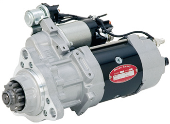
The Delco Remy 39MTTM heavy duty starter rotatable flange models were designed specifically to improve service flexibility and part number consolidation. The new service models provide full industry and application coverage, easily replacing competitive units. Plus, all new models are backed with our industry-leading, three-year/unlimited miles warranty.*
The rotatable mounting flange models can be rotated, or clocked, to take the place of many other fixed mounting flange starters. By utilizing these part numbers, you can reduce inventory part numbers while maintaining coverage for virtually all of the applications on the road today.
|
Delco Remy
Part Number
|
Voltage |
Teeth |
Pinion |
| 8200308 |
12V |
11 Tooth |
6/8 Pitch |
| 8200433 |
12V |
12 Tooth |
8/10 Pitch |
| 8200434 |
12V |
12 Tooth |
MOD3.00 Pitch |
| 8200330 |
24V |
11 Tooth |
6/8 Pitch |
| 8200435 |
24V |
12 Tooth |
8/10 Pitch |
| 8200436 |
24V |
12 Tooth |
MOD3.00 Pitch |
There are three key steps to keep in mind when clocking the starter:
- Obtaining the correct solenoid position
- Repositioning the Integrated Magnetic Switch (IMS)—if required
- Positioning the drain holes
You perform these steps to clear any obstruction that may hinder the starter from being mounted, such as the frame rail, bell housing, mounting brackets, hoses, lines or any other object that may be in or near the mounting area, and allow the starter to drain condensation properly.
Importance of Drainage Holes
The location of the drainage holes is important because if the drainage holes aren’t in the right location, the starter can take on water, which can lead to corrosion and contamination and early failure.
Two Ways to Properly Clock the Starter
There are two ways to clock the starter to fit your specific application.

OPTION #1
- Remove the old starter and place it on the workbench with the drive end housing facing toward you. This is the end where the starter pinion gear is visible.
- Place the new rotatable flange 39MT starter next to the old starter in the same orientation on the workbench in front of you.
- If the three (3) larger mounting holes are in the same place on both starters, then you will not need to clock the new starter.
- If they are different:
- Remove the six (6) torx [T30] screws on the front mounting flange.
- Turn the mounting flange until it mirrors the old mounting flange.
- Once the desired position is reached, reinstall and tighten the torx [T30] screws to 14-16 Nm (10.3 to 11.8 lb-ft).
OPTION #2
- If you don’t have the old starter, then hold up the new starter near the mounting area and look for any obstruction that could possibly interfere with mounting the starter in its current position.
- If there is an obstruction, hold the starter in the position that it will need to be mounted and remember that position.
- Place the new starter on the workbench and perform the steps for clocking mentioned in option #1.
- After properly clocking the starter to the correct position, you may mount the starter to the application.
Repositioning the IMS
Some applications require an additional step in order to properly clock and mount a rotatable flange 39MT starter because they have a much tighter fit between the frame rail and engine. As a result, the IMS needs to be moved to a different location on the starter.
If a properly clocked starter is not mountable due to interference of the IMS position, follow these steps.
- Remove the two (2) mounting screws on the IMS.
- Follow the wire leads from the IMS to the starter and solenoid. Then, loosen the terminal hold down nuts that go to each corresponding IMS lead. This will allow more flexibility when repositioning the IMS.
- Move the IMS to one of the six (6) mounting locations around the solenoid and starter motor body that allow for it to be out of the way of any obstruction that was preventing the starter from being mounted.
- Install the two (2) IMS mounting screws and tighten to the recommended specifications. Tighten the terminal hold down nuts that were loosened in Step 2.
- Reinstall the starter and check for proper position of the mounting flange and the IMS to make sure it is free from any obstruction.
If you have any questions regarding how to perform any or all of these steps, contact Technical Customer Service at 800-372-0222, or visit our support section on our website.
Point to Keep in Mind
The rotatable flange models will have a mounting hole diameter of .66 inches, while some of the fixed flange starters will have smaller diameter mounting holes. In this case, you will need to use larger head mounting bolts or use a grade 5 or harder washer on the starter mounting bolts to keep the bolt heads from pulling through the mounting hole. Both of these options are approved ways of correctly mounting a starter with larger mounting holes. It is not recommended to use hole sleeve spacers as this could cause issues with a proper flat mating surface between the starter mounting flange and the bell housing during installation.
* U.S. and Canada only